Description
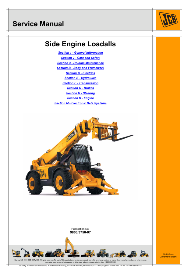
JCB Loadall Service Manual provides detailed workshop repair, maintenance, testing and technical information for the JCB side-engine telescopic handlers covered by publication 9803/3750-07.
This JCB Loadall Service Manual covers the following models:
• JCB 535-125 HiViz
• JCB 535-140 HiViz
• JCB 540-140
• JCB 540-170
• JCB 550-140
• JCB 550-170
The manual contains 1,758 pages of factory workshop information for professional mechanics, plant engineers, agricultural contractors, equipment owners and repair workshops. It provides procedures for routine maintenance, fault diagnosis, component removal, dismantling, inspection, testing, adjustment, repair, assembly and installation.
Different machine variants and specifications are covered throughout the publication. Application tables identify which procedures apply to each model, helping the user select the correct information for the machine being repaired.
General information
The general information section explains how to use the manual and identify the correct model and machine variant. It includes machine identification details, component identification plates, torque settings, hydraulic connector specifications, service tools, consumables, fuel information and stall-speed specifications.
The machine codes shown in the manual include:
• 5AF – JCB 540-170
• 5AG – JCB 550-140
• 5AL – JCB 540-140
• 5AM – JCB 550-170
• 5AN – JCB 535-125 HiViz
• 5AP – JCB 535-140 HiViz
Care and safety
The care and safety section contains workshop warnings, cautions and general procedures. It explains the precautions required when working with heavy components, hydraulic pressure, electrical systems, lifting equipment and raised machine assemblies.
Routine maintenance
The maintenance section provides service schedules and regular inspection information. Subjects include fluids, lubricants, capacities, cleaning, greasing, seat belts, ROPS and FOPS structures, brakes, electrical systems, engines, air filters, fuel systems, hydraulics, transmissions, tyres, wheels, wear pads and access panels.
Body and framework
Body and framework information covers the fork carriage, cab heating and ventilation, air conditioning, load moment indicator system, cab, fuel tank, chassis panels, boom assemblies, axle transducers and stabilisers.
The manual includes information for three-stage and four-stage boom arrangements where applicable to the individual models.
Electrical systems
The electrical section contains information covering fuses, relays, electrical schematics, harnesses, batteries, alternators and charging systems.
Detailed diagrams and testing procedures assist with tracing electrical faults and checking circuits, switches, sensors, connectors and related components.
Hydraulic systems
The hydraulics section covers hydraulic systems and schematics, control valves, servo controls, isolation valves, pumps, cooling-fan motors and hydraulic rams.
Repair information is included for extension, lift, tilt, displacement, sway and stabiliser rams. The section also provides hydraulic testing, fault-finding, removal, dismantling, inspection and assembly procedures.
Transmission and driveline
The transmission section includes wheels, tyres, front axles, rear axles, powershift gearboxes, bevel gearboxes, torque converters, oil coolers, propshafts and speed sensors.
The manual covers PS750, PS750 Mk IV, PS760 and PS764 gearbox systems where applicable. Application tables indicate the correct transmission information for each model and variant.
Braking systems
The brake section includes twin-axle service brakes, external and internal parking brake systems, parking-brake callipers, brake discs, switches, servo units, master cylinders and fluid reservoirs.
Procedures are provided for inspection, diagnosis, adjustment, component removal and repair.
Steering systems
The steering section covers manual and automatic steering modes, hydraulic steering units, priority valves, track rods, steering rams, steering columns and mode-control valves.
This information can assist with diagnosing steering faults and carrying out adjustments, testing and component repairs.
Engine information
The engine section covers mechanical and electronic fuel-injection versions of the JCB Dieselmax engine.
Information includes starting and stopping systems, cold-start equipment, starter motors, cooling packs, expansion tanks, air-filter switches, throttle controls, exhaust components and engine repair procedures.
Electronic data systems
The electronic data section covers the CANbus system, Loadall monitoring system, fault codes, ServiceMaster diagnostic equipment, electronic control units and pulse-width modulation.
This information is useful when diagnosing electronic faults, warning indications and machine-control problems.
Main manual sections include:
• General information
• Care and safety
• Routine maintenance
• Body and framework
• Electrics
• Hydraulics
• Transmission
• Brakes
• Steering
• Engine
• Electronic data systems
Manual details:
• Manufacturer: JCB
• Models: 535-125 HiViz, 535-140 HiViz, 540-140, 540-170, 550-140 and 550-170
• Machine type: Side Engine Loadalls
• Manual type: Service and Workshop Manual
• Publication number: 9803/3750-07
• Number of pages: 1,758
• Language: English
• Format: Digital PDF manual
The JCB Loadall Service Manual is supplied digitally. After purchase, you will receive an instruction PDF followed by a Filemail download link for the complete manual.
Please check your model, machine identification details and publication number before ordering, as different procedures may apply to individual models and production variants.
Reviews
There are no reviews yet.